| January 3, 2008 | HOME | ||||||||
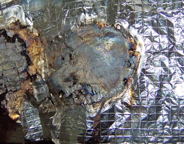
I believe that the firewall and forward floorboard insulation is highly fire resistant, but I do want a little better idea what that means. I set out to get an idea of that by putting a torch to it under conditions much less favorable that in the airplane. The picture below is of a second test with much the same results as the first. I just knew you would want pictures, so I did it again. I started with gas and air only.
after about 60 seconds, I added a little oxygen to bring the heat up and soon (90 seconds total) the oils began to burn out of the body material. It doesn't happen this way in the cockpit because there is no access to oxygen between the layers. I have one separate layer here.
Nothing much changed for 5 minutes, except that my hand started to get really hot.
At 7 minutes I quit. The backing on the other side had crumbled, but flame had penetrated the material. The central filling was charred and somewhat brittle. I could poke my finger through it, yet it kept the backside temperature at only a fraction of the applied heat. That's still hot, but not like a fuel fire!
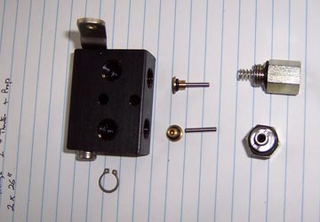
O. K. Back to what I was supposed to be doing. For my installation, the parking brake needs to draw from opposite side. I decided to turn the valve around in the parking brake housing. I mean, really, how hard can that be? Well, first obstacle was that my smallest snap ring pliers were too big for the holes in the snap ring. It had to come off the old fashioned way. It only took about 10 minutes to find it on the floor across the garage.
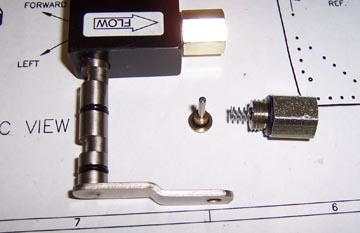
This is a view looking down the shaft hole. I have put it back together only to demonstrate where the pins are. They ride on a cam surface on the shaft.
These are the little parts that have to come out before you can remove the lever and cam assembly. Don't lose the snap ring! Use the proper tools!
The cam itself, has little o-rings on it that require a mediocre of care.
|
|||||||||
The process is simple. Just line up the parts in this order, slide the rod/cam back into the block, replace the small valve and rod (assuring that its little o-ring is in place) and reinstall the connectors with the springs facing the tops of the valves. If you take one apart, it will become obvious.
Ah, one little item I failed to mention; before assembly, check that the internal rods are aligned. They DO NOT center on the holes. You can tell when they are in the right place (off to the side), because they float freely and the valves can be fully depressed with something like a toothpick. Don't even think about asking me how it is I know this. On the other hand, the parts are cheap and the service from MATCO is spot on.
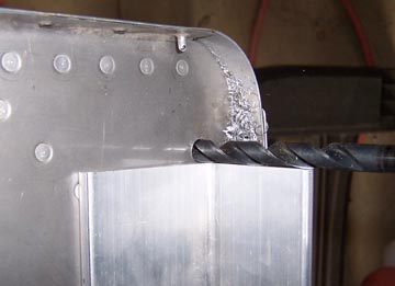
Having wasted lots of time already today, I wanted to do something that looked a little more impressive. I wanted to mount the motor mount to the firewall. I didn't have a clue what size drill to use, but I wanted the fit to be tight. I measured the bolt -- yes, I knew what size it was, but I wanted to know what size it really was...
Then I selected a drill that was a little undersized. My theory was that I could always ream it out, but couldn't add any back.
I went for simple with the alignment process using a 2 size under (from my target drill size) for a pilot.
The motor mount itself served to finish the alignment process and ensure that spacing was correct for this particular motor mount. You know, no matter how good the jig, welded frames always have some variation.
It worked! Surprisingly, the undersized drill made the holes just the right size. All 4 bolts are a stiff finger fit -- well they required a little something that I could push on so I didn't hurt my hand, but they fit perfectly!
Getting a head start on tomorrow (or the next day), I made this mounting plate for the Blue Mountain EFIS magnetometers and called it a day. Whew!
Previous Day | HOME | Next Day |
|||||||||
| ... | |||||||||