| January 15, 2008 | HOME | ||||||||
I started the day by screwing in the nose gear swivel stops. They are just a couple of allen screws that screw into the nose gear yoke. The heads of the allen screws form serve as the blocks that fit against the stops.
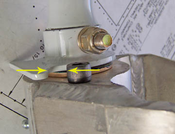
Here is a picture of the how the stop nuts approach the stop bracket to limit the travel of the nose wheel. I do know of one RV builder who has ground the bracket back to allow much more travel in the nose wheel. I happen to think that is a really bad idea, but to each builder belongs the opportunities.
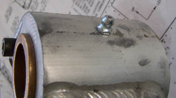
I also installed the zerk fitting on the nose wheel yoke. I have been asking people what is the origin of the term, "zerk" for a grease fitting. Most folks say it is just slang or a made up term. I think it's no coincidence though that the patent for the zerk fitting was granted to Oscar Zerk in January 1929. Ya tink maybe dats where it come from?
I slipped yoke onto the nose gear and started the nut to hold it in place. I'm not quite ready for final assembly.
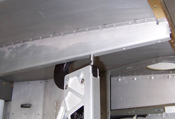
One of the issues you occasionally see with RVs is bent armrests. That usually happens when a passenger steps on he armrest getting out of the plane. It can even happen if someone lifts himself by putting a hand on the armrest and pushing as they get up. Following what some other builders have done, I decided to brace the armrest with a little extra material under the lip. I spaced out rivet points at about 1 1/2 inches.
I drilled the rivet points with a #40 and put my brace material in place and match drilled the holes through both.
|
|||||||||
For support material I used a double piece of 1/2x1/2x032 aluminum angle. This is not particularly strong compared to heavy extruded angle some builders are using, but I felt it was a good compromise between strength and weight. Besides, if the material is too strong and someone really abuses the armrests, they could tear out at the rivets at each end. That would be a much more difficult repair.
Finally, I riveted it all in place. I was happy to see that the armrests didn't look any different, but I new they were a little stronger than original.
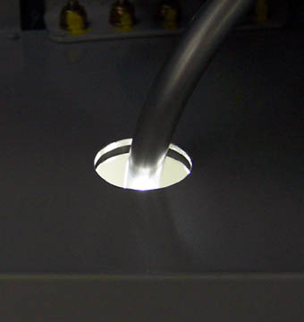
Getting back to cabin fuel plumbing, I cut the holes in the sidewalls and routed the 3/8" tubing through. I was careful bend it in such a way that it lay naturally in the center of the hole where a rubber grommet will fit around it.
At the other end of cabin fuel line that runs along the spar, I mated them up to the fuel valve. There seems to be no elegant way to guide these lines through the various bends, but as long as the bends remain relatively smooth, it's good.
Next, I installed the boost pump assembly (after double checking that all connections were tight) and fitted it all to the fuel valve.
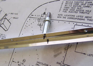
In both this picture and the one above, you can see the fuel flow sender. I had originally mounted it on the firewall inside the cabin, but I couldn't really work out how to get a good straight run of tubing on both sides of it. Having bends too close to the sender can cause turbulence in the flowing fuel and affect the accuracy of the fuel flow readings. I decided to fix it while it was relatively easy to do and before it became a problem.
Previous Day | HOME | Next Day |
|||||||||
| ... | |||||||||