| December 7 , 2008 | HOME | |||||||||
The serious wiring begins with a relay bank to switch functions between controlling MFDs. Functions like altimeter settings, gps steering, radio frequencies etc. must come from only one MFD. If the plane will be flown from either the left or the right seat, making the left or right MFD (according to which is the active pilot seat) controlling makes sense. This relay bank will act as the switch to make that change, though not normally while in flight.
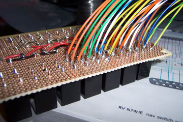
The relay terminals project through this piece of blank computer circuit board, so they can be soldered according to the diagram or schematic.
The soldering begins. Color coding the wire helps keep things in order and should be helpful in the very unlikely event that service is required.
Below is the schematic (yea, more of a diagram) I am following in building the relay block. As the soldering begins a few little glitches become apparant. That means adjusting the diagram.
The finished relay bank with DB connectors yet to be wired.
The first of 6 DB connectors is pinned according to the wiring diagram paying strict attention to the color coding.
|
The majority of the DB connectors are crimp type like these which lead from the relay block.
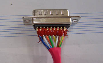
There will be only a couple of solder type connectors like this high density connector that connects to the Blue Mountain box.
The first of the wiring harnesses, these to the Blue Mountain units, are complete. These were done first because they were relatively simple.
Each Blue Mountain requires a resistor between 1 and 2 and 5 and 6 of the respective 25 pin DB connector. A little piece of shrink tubing will protect the solder connections.
Previous Day | HOME | Next Day |
|||||||||
| ... | ||||||||||